
The Trace Elliot Speed Twin are a series of amps includiung a C30 (30 watt combo based around 4 x EL84) and 50 or 100 watt combo and head variations based on EL34 either pair or quad respectively. They have two channels and the usual features one would expect in a modern amp plus a few unusual features. Designed in 1996 and redesigned in 1998 to comply with EU emission standards, improved fusing and some improvements in PCB layout they have some great features and supporting information and are solidly built.
Although PCB based great care has been in the circuit layout to minimise hum and pickup typical in hand wired amps through poor lead dressing. There are two circuit boards one for the pre amp and one for the power amp – these components seem to be shared with other Trace models e.g. Bonneville according to the circuit diagram at least. I have found that the PCBs are a little cramped in places and the circuit board pads not the most resilient. However I would say that these amps are good quality and their unique features make them well worth a look.


What I like about these amps is that the bias is adjustable from the back in a safe manner (well the MkII are) meaning that anybody can do the adjustment with a cheap multimeter and a screwdriver and the supporting instructions make it very clear. Also they support different power valve types e.g. EL34 and 6L6 and power levels – I love this idea very flexible and also switched pentode / triode operation. Great for people who want to experiment with sound and for recording. Note the Mk I must be bias adjusted using bias probe as their is no measurement resistor.
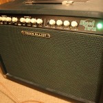
I was lucky enough to take a look over a C50 speed twin combo this week. The fault was that it went bang after being left on for three days accidentally and as the owner turned it back to standby so there was a bang and a dead amp.
Upon opening up the amp which is extremely heavy and well made I immediately looked round for the source of the bang. It turned out to be a group of four diodes near to the power valves – a bridge rectifier. Not uncommon for these to burn out in response to a downstream short e.g. from a smoothing capacitor or in this case the 7824 regulator – the supply for the channel switching relays.
I had picked up a circuit diagram from a forum for this amp but kept finding inconsistancies e.g. missing fuses and different component values which made me think I was not looking at the correct diagram. However my experience contacting traceelliot / peavey for the correct diagram was a joy – see below for more on that. But first the repair details.
Replacing the four 1N4002 diodes (1A general purpose rectifying diode) was fairly straightforward apart from having to remove the smoothing capacitor nearby to get access. Although pad damage was inevitable as the plate-through holes were barely big enough to accomodate the diode leads does raise the question of layout design. I mean this amp is massive, there is no shortage of space inside yet the PCB are squashed in places. Like all things I am sure there is a good reason. Powering up the amp (without power tubes in just in case) revealed that the diodes were working ok and checking the 24 volt supply all seems good. However upon fitting the original (13 year old valves) I discovered that one was open circuit on the heater filament. So perhaps that is the cause of the issue. . . Ordered a set of Harma from Watford Valves and then we are good to go.
What was interesting in this amp was my experience in dealing with Trace Elliot or Peavey as they seemed to be owned by now. I contacted them one morning for the circuit diagram (not expecting much help) and got this fantastic response – in just two and a half hours.